G4BAO
Microwave amateur radio station at Waterbeach, 8 km north of Cambridge. Locator JO02cg.
- 50 MHz
- 70 MHz
- 144 MHz
- 432 MHz
- 1296 MHz
- 5760 MHz EME
- 10368 MHz EME
- 24048 MHz
News
Updated 30th october 2026
New website still under construction
Hopefully still carrying the same information as the old one and a bit more
23 and 70cm driver kits are no more
The LDMOS device PD85004 used in my 23 cm 3 W driver kits is obsolete, and there has been no new stock anywhere for around three years apart from some on AliExpress. I therefore can no longer sell 23 cm kits and I am also ending sales of 70cm kits.
I have just 2 of each full kit left which I wil ship on a "first come (pays!) first served" for £30 all in to UK only. (1 per person)
I do have a few blank PCBs left for each which, if you send me a small strong envelope with your address on it and stamped with enough postage, I'll put a PCB in it and return it for no charge. Again 1 per person and "first come first served" but check by email first, (bottom of this page) that I still have any left.
I will announce on here when they have all gone.
The newer 70 cm kits have an on-board bias regulator and use an alternative device in the same package, with slightly lower gain: about +14 dBm drive (without the 3 dB input attenuator) gives 3 W Psat. It can’t do useful gain or power at 23 cm, and I haven’t found a replacement. The 23 cm article, build guides, Eagle files and Gerbers are archived on GitHub, and I'll shortly add the 70cm details.
Talks and books
- My RSGB Convention 2022 talk, “GHz Bands EME from a ‘challenging’ location”, is on the Downloads list.
- My 2015 and 2016 RSGB talks, on meteor scatter and moving up to 23 cm, are on the RSGB YouTube channel.
- The UKuG Backscatter book is free to download: 445 A5 pages of the best Scatterpoint articles from 1999 to 2006, covering frequency sources, antennas, LNAs, PAs, transverters, measurement and more.
On the air
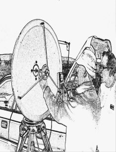
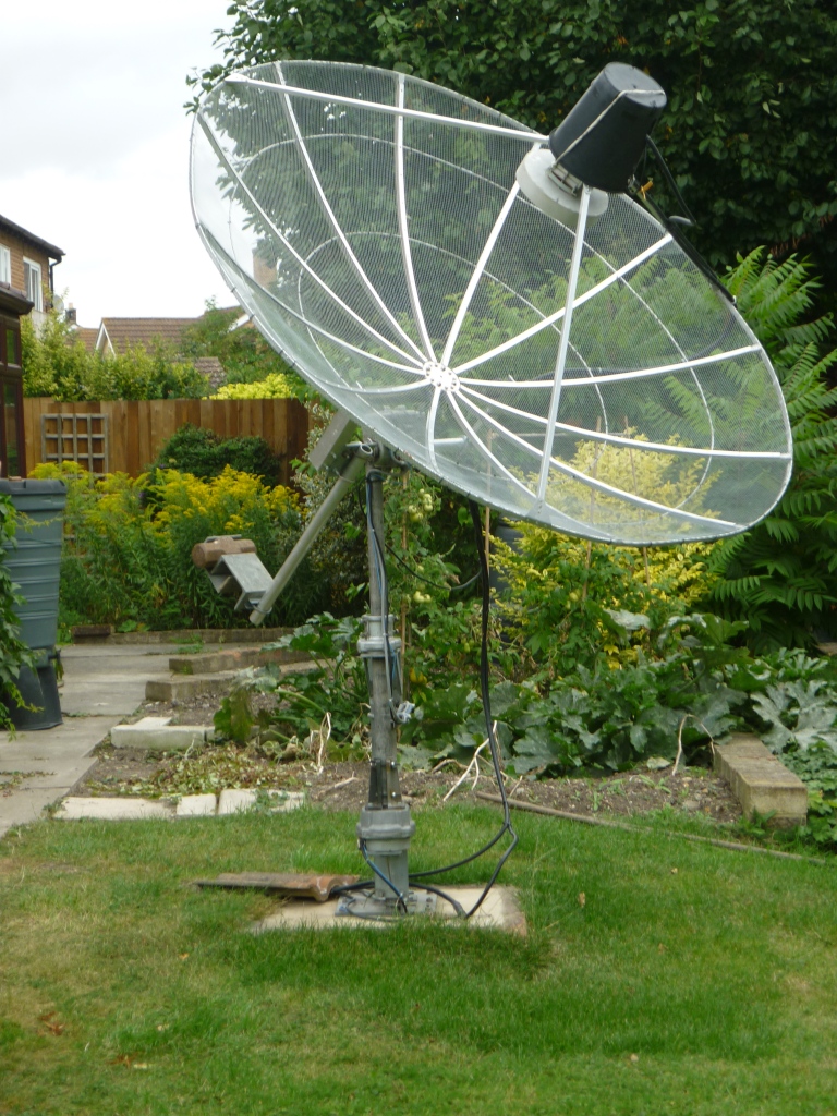
I’m QRV on 5.7 and 10 GHz EME and on 432MHz, 1.3, 10 and 24 GHz terrestrial. For 10GHz EME I run 30W and on 5.7GHz 25W to 1.2 m solid offset dish with Chaparral and RA3AQ Septum +horn feeds respectively.
Around Waterbeach

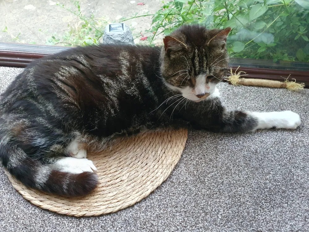 Oliver is getting old these days!

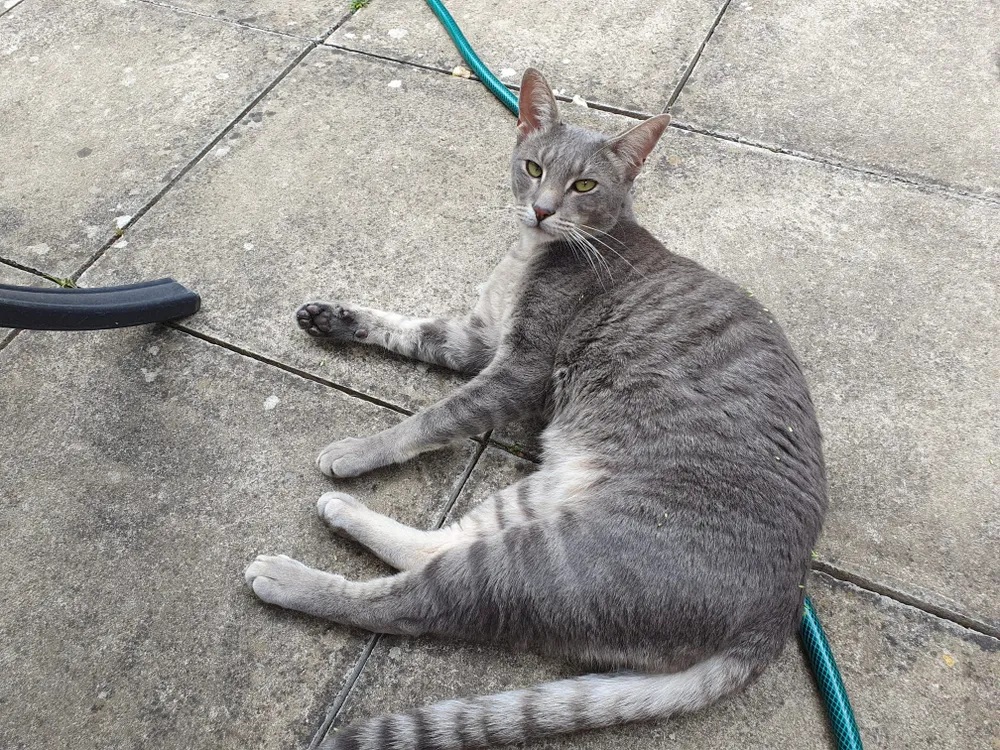 And he now has Archie Gray deal with

About me
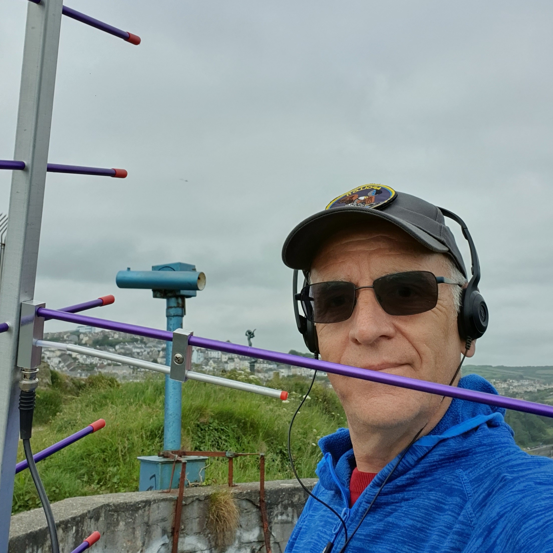
I’m John Worsnop, a retired Chartered Engineer. I was first licensed in 1971 as G8EQR, and became G4BAO in 1972 after passing the old Post Office Morse test.
My interests are technical, mainly VHF and UHF, including EME, where I have made Moonbounce QSOs on all bands from 432 to 10GHz with small backyard systems. I have a passion for radio propagation and weak-signal working.
I have been the RadCom "GHz Bands" columnist since January 2013.
I built and maintain the 24GHz microwave beacons GB3CAM and GB3PKT and the Kent 24GHz WebSDR.
At Pye Telecommunications in the 1970s I worked professionally on low capacity microwave link equipment, and designed and built the power amplifier and duplexer for GB3PT, the UK’s first RTTY repeater, and the transmitter for the 70 MHz beacon at Crowborough.
After moving in to academia for nine years I returned to the wireless industry with Spectronics Microsystems, MDSI and Digital Dispatch, finishing my career at Splashpower, the startup that pioneered wireless battery charging.
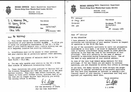
In the 70s and 80s my Amateur Radio activities focused on 70 MHz, and was active on 28/50 MHz crossband in Solar Cycle 21. In 1983 I was one of the “Fortunate Forty” who were issued the first permits to operate on 6 metres in the UK.
My PhD thesis, A Study of the End Point Geometry in Meteor Burst Systems (CNAA 1990), is a lost classic. There is now a searchable PDF, thanks to Marcus Walden G0IJZ for photographing each page and his colleagues at Plextek for the indexing.
Station
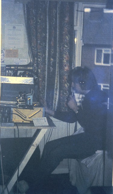
My current set-up, though not all at the same time.
| Band | Equipment |
|---|---|
| 50 MHz | FTX1-Field with homebrew 300 W LDMOS PA to a 5+5 element YU7EF dual-band Yagi at 10 m |
| 70 MHz | FTX1-Field with homebrew 150 W LDMOS PA, same YU7EF Yagi |
| 144 MHz | IC9700 to a loft mounted bidirectional 2el Yagi or Diamond V2000 triband vertical |
| 433 MHz | IC9700 70 W, to a 18 element Wimo Yagi at 8 m or Diamond V2000 triband vertical |
| 1296 MHz | IC9700, 500 W LabTech AB LDMOS amplifier, G4DDK VLNA2+ preamp (0.29 dB NF), 44-element Wimo Yagi |
| 5760 MHz EME | K3, Anglian 144, Kuhne G3 5.7 GHz transverter, DU3T preamp, Homebrew 2 x Ferranti 12W GaAsFET PAs, 120 cm offset dish with RA3AQ Septum feed |
| 10368 MHz | K3, Anglian 144, GW4DGU 10 GHz transverter, 0.7 dB NF preamp, Marconi-Matra 14 W GaAsFET PA (7 W at the feed), 60 cm offset dish with W1GHZ 10G/24G feed |
| 10368 MHz EME | K3, Anglian 144, Kuhne G5 10 GHz transverter, DU3T 0.7 dB NF preamp, Homebrew 2W W GaAsFET PA, 120 cm offset dish with Chapparal feed |
| 24048 MHz | K3, Anglian 144, Kuhne 24G2 masthead transverter, 2.2 dB NF preamp, 25 W GaAsFET PA, 60 cm dish with W1GHZ feed |
| References | G3RUH GPSDO 10 MHz, and a 127.5 MHz G8ACE oscillator ref-locked to it |
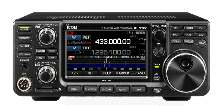 Icom IC9700
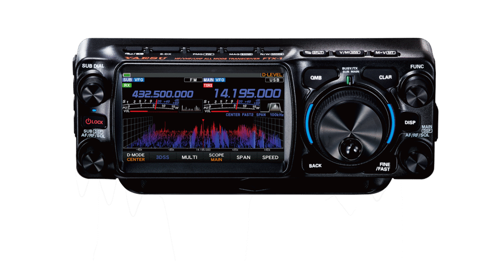 FTX-1 Field
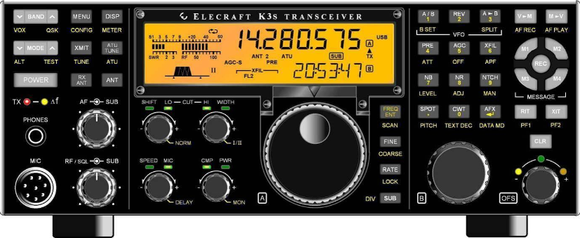 Elecraft K3
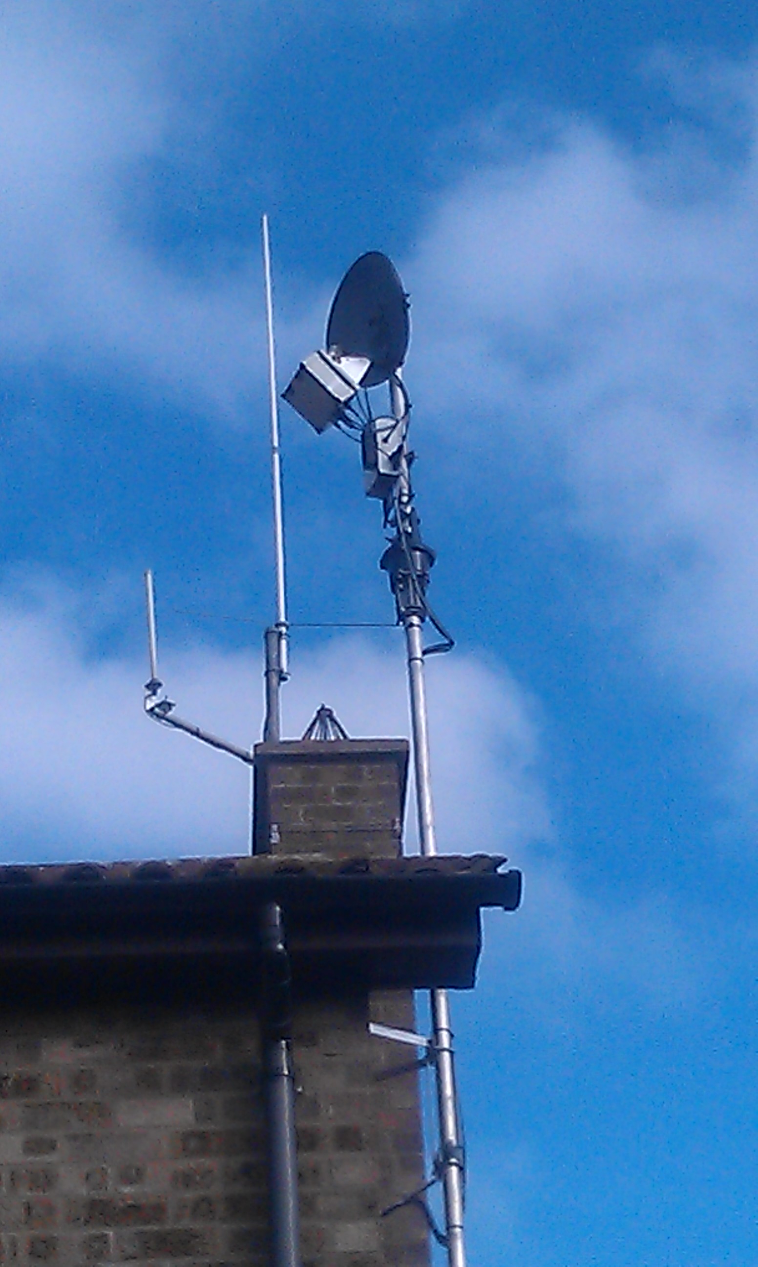
Projects
These are some of the many Amateur radio projects I've done over the years. They’re descriptions of what I did, not finished articles. Links to detal are provided.
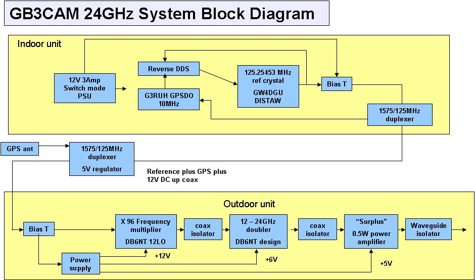
GB3CAM 24 GHz beacon24048.870 MHz, GPSDO locked, 250 mW
The idea came from musings on the success of the 10 GHz beacon, in emails between Bernie G4HJW, Sam G4DDK and me in August 2007. I already had a 12 GHz multiplier, and Chris GW4DGU wanted to try his ultra-stable “DISTAW” oscillator. From concept to on air took 13 months. GPS locking in May 2010 made it, as far as I know, the first 24 GHz beacon in the world to run JT4G.
- Even minutes: “GB3CAM JO02BI” in JT4G, then “GB3CAM” in Morse.
- Odd minutes: unmodulated carrier until 32 seconds past, then “GB3CAM” in Morse.
- JT4 tones: 24048.869798, .870113, .870428 and .870743 MHz. CW key-up tone is 24048.8696 MHz.
- Site: Haddenham Cambridgeshire, JO02BI. Horizontally polarised 10 dBi slotted waveguide at 10m AGL, in a clover-leaf pattern.
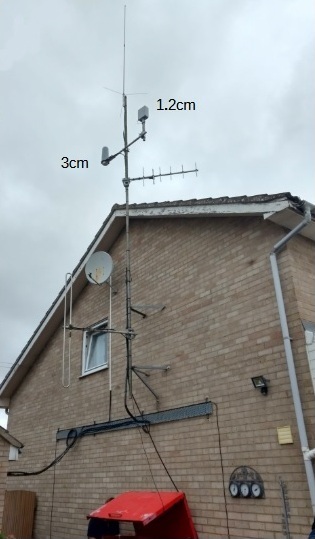
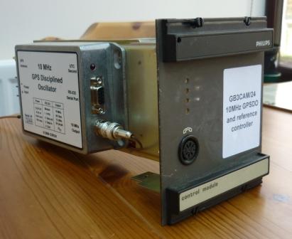
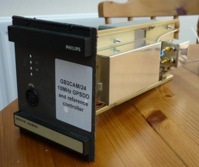 The GPSDO and reference controller
The Margate 24 GHz WebSDRStudying trans North Sea propagation
Site: Invicta House, Margate Kent, JO01QJ81.
Antenna: Horizontally polarised 15 dBi 90 degree sector antenna at 80m AGL, pointed at Rotterdam.
Here is a link to the full description of the WebSDR
https://g4bao.com/Kent WebSDR_1.pdf
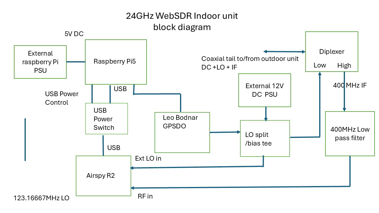 Indoor Unit Block Diagram
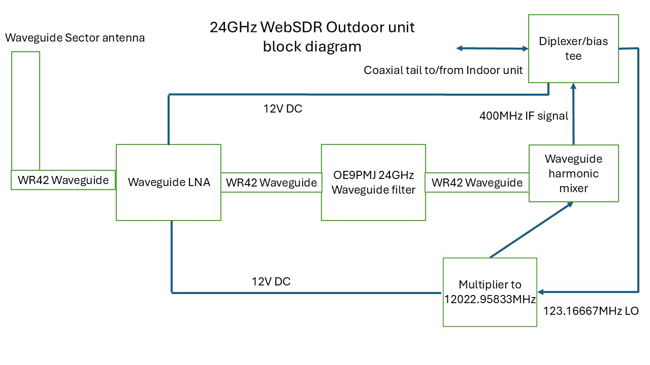 Outdoor unit Block Diagram
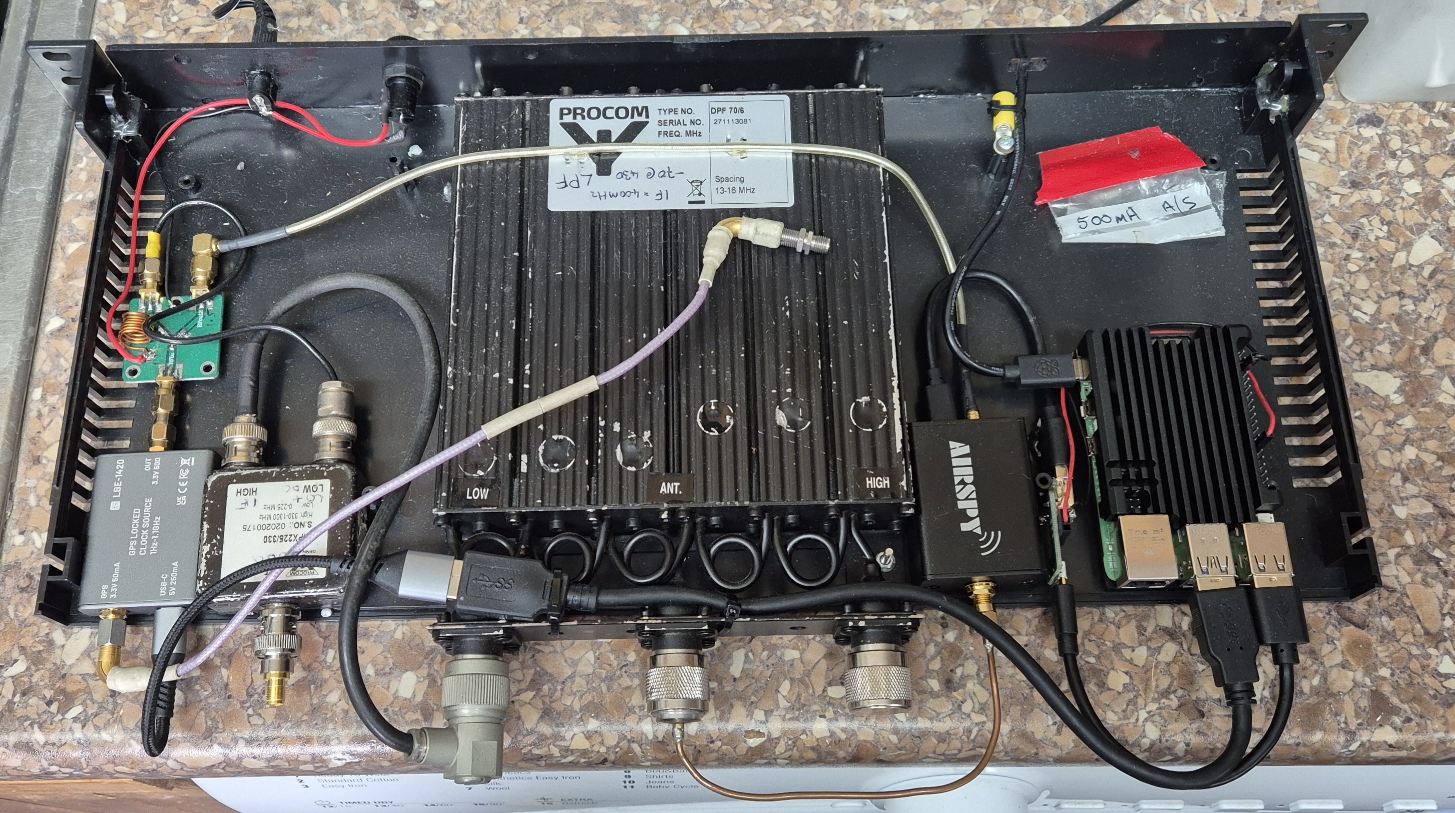 The Indoor unit
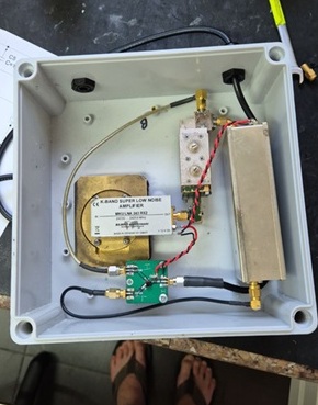 The Outdoor unit
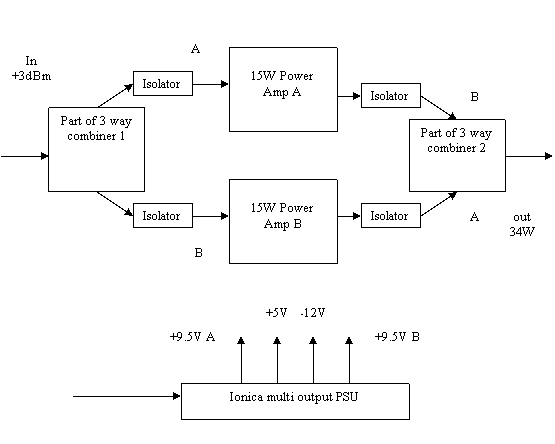
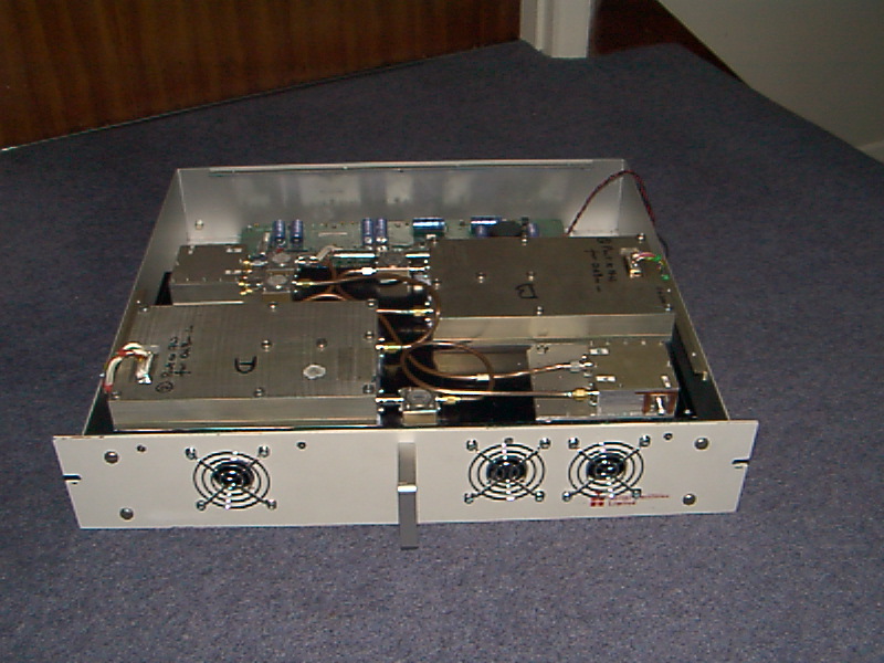
34 W 3400 MHz PA from surplus Ionica unitsTwo 19 W amplifiers combined
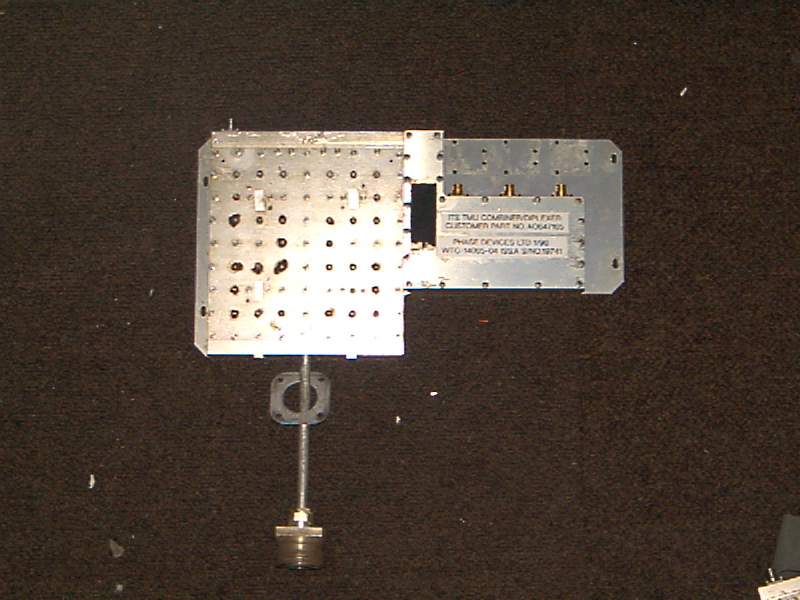
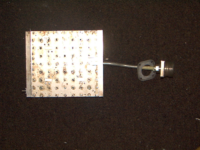
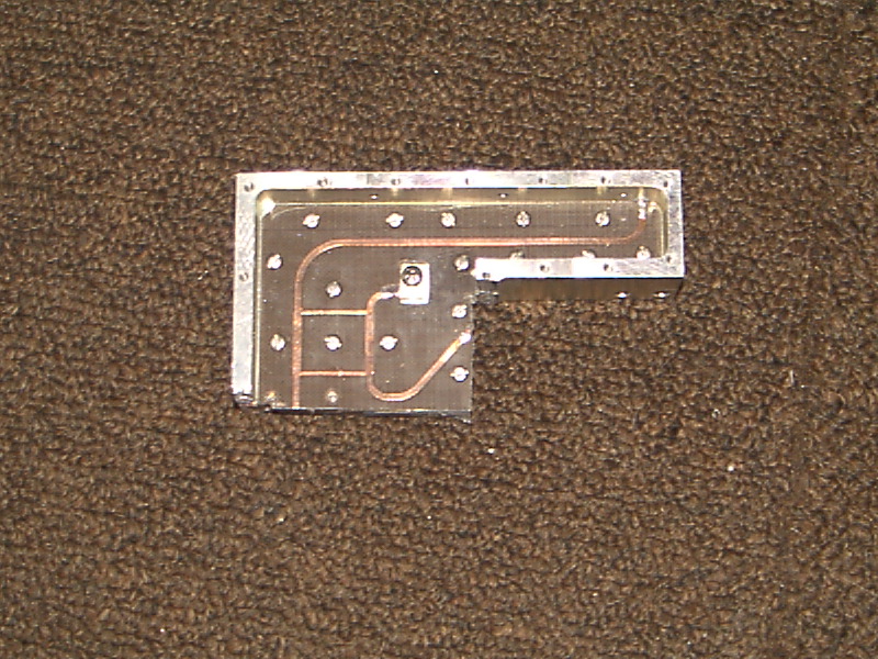
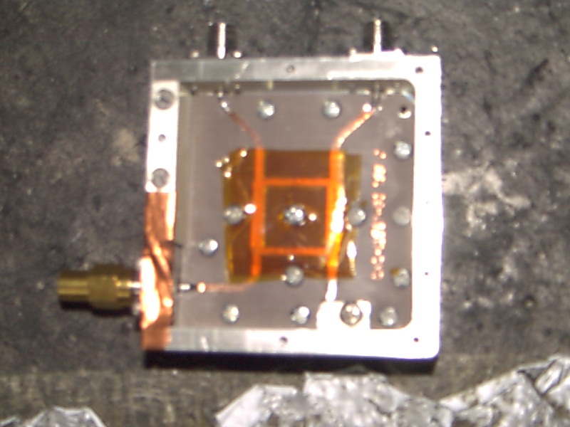
Two Ionica base-station PAs, joined with hybrid combiners made by cutting the surplus 3-way combiners down to 2-way. Three layers of Kapton tape on the hybrid pull it from 3600 down to 3400 MHz, and the duplexers retune as 3400 MHz band-pass filters.
- 2 mW in gives 19 W from each PA and 34 W combined, drawing 3.2 A at 48 V (154 W).
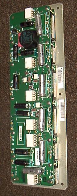
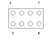
- The supply is the Ionica’s six Nemic-Lambda PH modules: 9.5 V modules for the PAs, run from an unregulated 35 to 50 V at about 4 A.
- Semi-rigid SMA leads must be exactly the same length either side of the amplifiers, to keep the phase relationship.
- Hybrid tests at 3400 MHz: input return loss 26 to 27 dB, insertion loss about 3.2 to 3.3 dB.
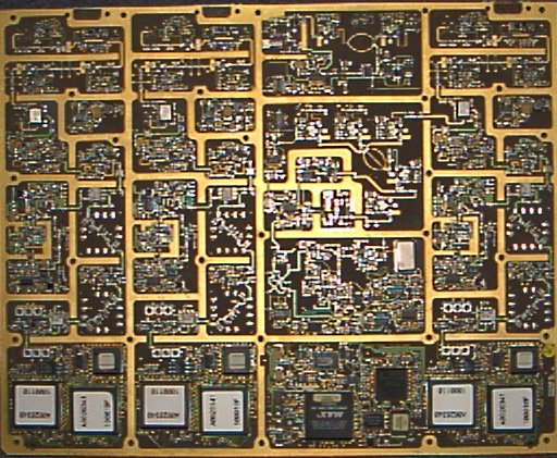
9 cm transverter from the Ionica “big board”About 5 mW out, around 3.5 dB noise figure
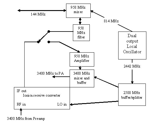
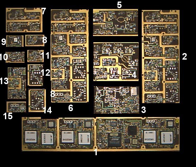
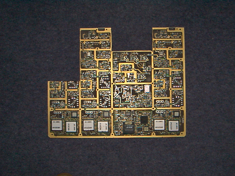
The Ionica base station has a single PCB with three complete double-conversion transmit strips, once seen at rallies for £1. I cut out the main upconverter and used it with an Ionica receive converter.
- Oscillator: 90.444444 MHz crystal ×9 to 814 MHz, then ×3 to 2442 MHz.
- Replace the first IF filter with a 958 MHz helical or SAW filter. The Ionica “pizza box” has an identical one.
- The PIN diode attenuators need 10 V to forward bias them, or remove the diodes and bridge the tracks.
- Solder vertical screens along the gold borders, or 3256 MHz (2442 + 814) leaks into the output. Check it on a spectrum analyser before going on air.
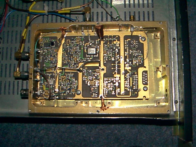
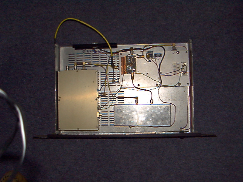
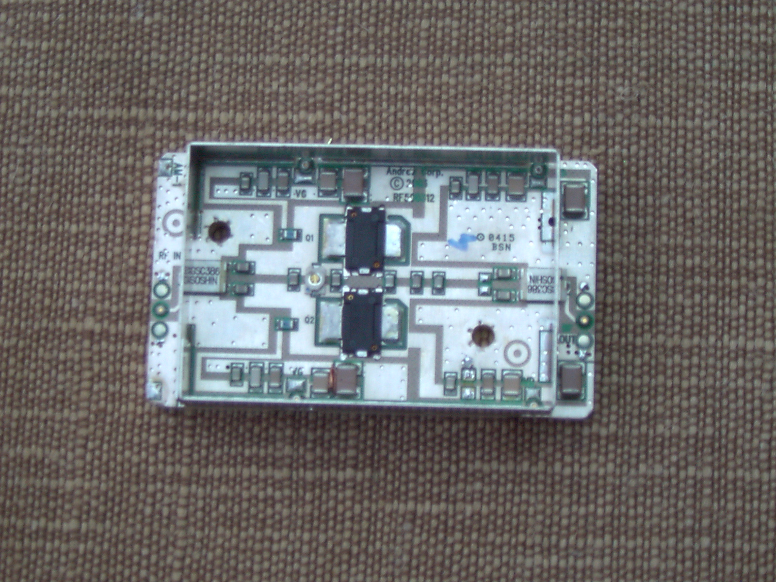
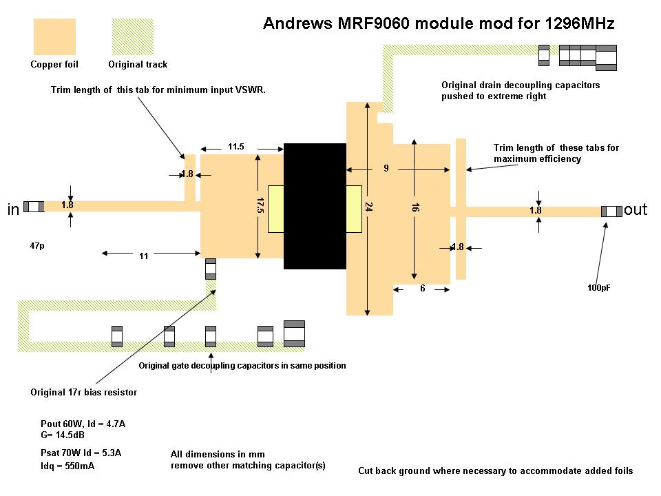
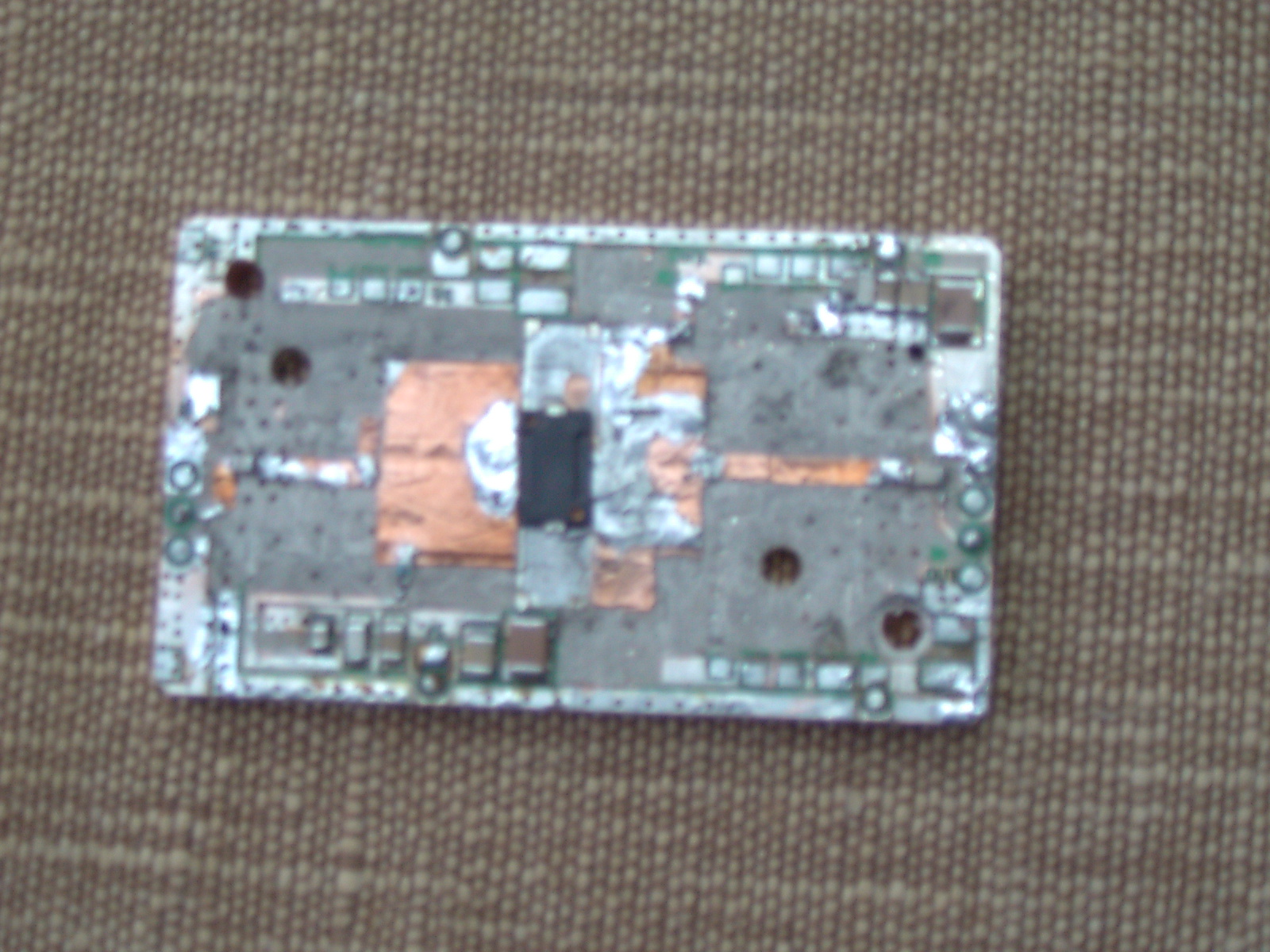
70 W and 35 W 23 cm PAs from Andrew 900 MHz modulesMRF9060 and MRF9045 LDMOS, 28 V
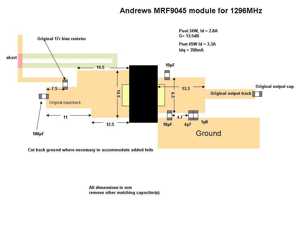
Surplus Andrew cellular PA modules, rebuilt with copper-foil matching lines worked out in Appcad and a Smith chart program, since there is no impedance data above 960 MHz. For the MRF9060 module I reduced it to a single device.
- Results: about 70 W from the MRF9060 at 5.3 A and 35 W from the MRF9045 at 3.3 A.
- Bias: start at zero gate volts, then set the quiescent drain current to 350 mA (9045) or 450 mA (9060).
- Always disconnect the drain and gate supplies before trimming the foil, and trim no more than half a millimetre at a time.
Downloads
3 W 70 cm amplifier
Also a 500 mW DATV amplifier. PCB kits are on the Kits list.
2.5 W 23 cm amplifier
No longer available as a kit.
Presentations and papers
- GHz Bands EME from a “challenging” location (RSGB 2022)
- The Bodger’s Guide to QO-100 / Es’hailSat
- Moving up to 23 cm (RSGB 2016)
- A deeper understanding of meteor scatter (RSGB 2015)
- VHF propagation (RSGB 2013)
- Optimising a REALLY small microwave EME system
- Modifying 1960MHz High Power Solid state Amplifiers for 13cm (EME2012 paper)
- The Bodger’s Guide to Amateur Microwaves ( CUWS 2012
- The Bodger’s Guide to Solid State QRO (Orebro EME 2011 paper
- The Bodger's Guide to Patio Moonbounce
- The Bodgers Guide to Solid state QRO at VHF (RSGB 2010 paper)
- The Bodgers Guide to Scattering Parameters (RAL 2010 paper)
- The Bodgers Guide to LDMOS Power Amplifiers(RAL 2009 paper)
- The Bodgers Guide to Using ceramic flange mount devices in the G4BAO 23cm LDMOS PA
- The Bodger’s Guide to Recycling Aerial Facilities 900MHz quadrature hybrids for 23cms.
- The Bodger’s Guide to Recycling a Mini Circuits ZAPD1 0.5-1GHz power splitter.
- The Bodger’s Guide to A 40 Watt power amplifier for 2320MHz using the MRF19085 in a G4BAO 1296MHz board
- Code to play with for programming the synthesisers in Ionical equipment
- Backscatter 1st Edition Errata— to be inserted after p347
Links
- Microwaving my Cat, my blog
- UK Microwave Group
- Camb-Hams, probably the best radio club in the world
- G4DDK, low-noise amplifiers and transverters
- WA5VJB, printed circuit antennas
- ON4KST microwave chat
Kits
The last few 23cm and 70 cm driver amplifier PCB kits: £30, including first-class postage in the UK. Tinplate boxes and connectors for it are available from Alan G3NYK, box 1000102.
Please order by email. I only ship to the UK, and PayPal payments are accepted in pounds sterling only.
Contact
Email me at john at g4bao dot com, or find me on the ON4KST microwave chat. My station is at Waterbeach, JO02cg.